Wednesday, December 29, 2010

5

MICROSOFT ROBOTICS DEVELOPER STUDIO + OPENCV

In a previous post I explained how to add a simulated stereo camera to your simulated robot. OK! Having a stereo camera is fun... but, process the images and getting some interesting results is even funnier!!

Now, you could implement several Computer Vision techniques by yourself or take advantage of existing libraries.

For that matter, one of the most used libraries for computer vision is OpenCV. There is only a small problem... OpenCV is intended to be used under C/C++ and Microsoft Robotics Developer Studio is programmed in C#.

The solution to that problem is called EmguCVEmgu CV is a cross platform .Net wrapper to the Intel OpenCV image processing library. Allowing OpenCV functions to be called from .NET compatible languages such as C#, VB, VC++, IronPython etc. The wrapper can be compiled in Mono and run on Linux / Mac OS X.

In order to use it in your MRDS projects you should:

1. Install EmguCV
2. Add a reference to Emgu.CV and Emgu.Util to your project in Visual Studio.


3. Add the needed "using" statements at the beginning of your source code


using Emgu.CV;
using Emgu.Util;


And that is it. Now you can use all the functionality of OpenCV in your robots (real or simulated).

Sunday, December 26, 2010

1

MRDS: MOBILE BASE + ROBOT ARM

Today I would like to explain how to attach a robot arm to a mobile base using the simulation environment of Microsoft Robotics Developer Studio. It is a very simple task but it can get a bit tricky.

I have been following the examples and explanations on the book Professional Microsoft Robotics Developer Studio (you can find the source code of the examples at http://www.promrds.com ). In this post I will explain how to attach a Simulated LynxL6Arm to a simulated Corobot

First of all, you should open in Visual Studio the project where the Corobot Entity is defined and add a reference to SimulatedLynxL6Arm.Y2007.M07. 


Then edit the file Corobot.cs and locate the definition of the constructor public CorobotEntity(string name, Vector3 initialPos). At the end of the constructor insert an instance of the robotic arm like this:

//Insert the LynxL6Arm
LynxL6Arm.SimulatedLynxL6Arm l6arm = new LynxL6Arm.SimulatedLynxL6Arm(name + "_arm", new Vector3(0,0,0));
l6arm.State.Pose = new Pose(
        new Vector3(0, 0.23f, 0),
        Quaternion.FromAxisAngle(0, 1, 0, (float)(-Math.PI / 2)));


InsertEntityGlobal(l6arm);


Now, compile the project and run it. You should see something like this:


That was easy, wasn't it? But now, if you try to drive the Corobot around you will find that IT WONT MOVE! You will see the wheels spinning, but the robot doesn't move an inch from its position. WTF!

Now is when one becomes crazy trying to find out what is going on. You start reading MRDS's forums and find answers as crazy as "copy the source code of the definition of the robot arm inside the definition of the mobile base"... WHAT?? Come on! There must be a more elegant solution!!

And, indeed, there is. It took me one whole day to find out what was happening but, if you take a deep breath and focus, you eventually find the solution.

If you look to the picture above (the one with the Yellow Lynx L6 Arm on top of the Corobot) you will notice that it has a cylindric base. Well, that base is, by default, defined to be Kinematic, that means that it will not follow the physic laws and will stay like sticked to the ground. That is why the robot will not move!

Now, the solution to this problem is to remove the kinematic flag from the arm instance that we just created. So the correct source code looks like this:


//Insert the LynxL6Arm
LynxL6Arm.SimulatedLynxL6Arm l6arm = new LynxL6Arm.SimulatedLynxL6Arm(name + "_arm", new Vector3(0,0,0));
l6arm.State.Pose = new Pose(
        new Vector3(0, 0.23f, 0),
        Quaternion.FromAxisAngle(0, 1, 0, (float)(-Math.PI / 2)));

//Remove the Kinematic flag!! Otherwise the mobile base gets stuck!
l6arm.State.Flags = l6arm.State.Flags & ~(EntitySimulationModifiers.Kinematic);
InsertEntityGlobal(l6arm);


Tuesday, December 21, 2010

2

KINECT: HELLO WORLD


The first shot taken with Microsoft Kinect. Thanks a lot to Fukui-sensei for providing such a nice tool.

Sunday, December 5, 2010

2

MRDS: SIMULATED STEREO CAMERA

During the last few weeks I have been working with Microsoft Robotics Developer Studio, it incorporates a very powerful simulation environment that enables you to visualize your robot and even program it even before actually building it.

By default a lot of simulated entities, basic for robotics, are provided: Simulated IR Distance Sensor, Simulated Sonar, Simulated Webcam, Simulated GPS Sensor, Simulated Laser Range Finder, etc...

But I was missing another basic entity often used by robots: A Stereo Camera. After reading some posts at MRDS forum I could not find a suitable solution (easy and fast to implement), so I just built my own solution.

If you want to simulate a stereo camera on Microsoft Robotics Developer Studio, you can follow this 3 steps:

Step 1- Add this class to your project:


public class StereoCameraEntity
    {
        public CameraEntity leftCam;
        public CameraEntity rightCam;
 
        public StereoCameraEntity()
        {
        }
 
        public StereoCameraEntity(
            String parentEntityName,// The name of the parent entity (used to generate a unique name) 
            int viewSizeX, //Image width  
            int viewSizeY, //Image height 
            float viewAngle,//View angle of the camera in degrees  
            Vector3 position,//Position of the center of the stereo camera 
            float baseLine,//Distance between the center of the cameras in centimeters 
            bool isRealTime)//Renders every frame 
        {
            //Initialize left camera 
            leftCam = new CameraEntity(
                viewSizeX,
                viewSizeY,
                (float)(viewAngle * Math.PI / 180.0));
            leftCam.State.Name = parentEntityName + "_LeftCam";
            leftCam.IsRealTimeCamera = isRealTime;
            leftCam.State.Pose.Position = new Vector3(
                position.X - (baseLine / 100.0f) / 2.0f ,
                position.Y,
                position.Z);
 
            //Initialize right camera 
            rightCam = new CameraEntity(
                viewSizeX,
                viewSizeY,
                (float)(viewAngle * Math.PI / 180.0));
            rightCam.State.Name = parentEntityName + "_RightCam";
            rightCam.IsRealTimeCamera = isRealTime;
            rightCam.State.Pose.Position = new Vector3(
                position.X + (baseLine / 100.0f) / 2.0f ,
                position.Y,
                position.Z);
        }
    }

This class is just a wrapper for CameraEntity. When calling the constructor for the new class that you just created you need to provide:

  • parentEntityName: A string containing the name of the parent entity (It will be used to create a unique name for the cameras)
  • viewSizeX: An integer for the horizontal resolution of the cameras (In pixels).
  • viewSizeY: An integer for the vertical resolution of the cameras (In pixels).
  • viewAngle: A float for the view angle of the cameras (in degrees).
  • position: A Vector3 containing the position of the stereo camera (in meters).
  • baseLine: The separation between the cameras (in centimeters).
  • isRealTime: True to render every frame.
Step 2- Inside the constructor of your entity create a new StereoCameraEntity and insert it as a child:

StereoCameraEntity stereoCam = new StereoCameraEntity(
        name,
        320,
        240,
        30.0f,
        new Vector3(
                xLocation,
                yLocation,
                zLocation),
        10.0f,
        true);
InsertEntityGlobal(stereoCam.leftCam);
InsertEntityGlobal(stereoCam.rightCam);

This creates a new stereo camera with a resolution of 320x240 pixels, a field of view of 30 degrees, a base line of 10 centimeters, located at the point (xLocation, yLocation, zLocation) and rendering every frame.

Step 3- Modify the manifest of your project to include this:


<servicerecordtype>
        <dssp:contract>http://schemas.microsoft.com/2006/09/simulatedwebcam.html</dssp:contract>
        <dssp:service>http://localhost/MyRobot/LeftCam</dssp:service>
        <dssp:partnerlist>
          <dssp:partner>
            <dssp:service>http://localhost/MyRobot_LeftCam</dssp:service>
            <dssp:name>simcommon:Entity</dssp:name>
          </dssp:partner>
        </dssp:partnerlist>
      </servicerecordtype>

     <servicerecordtype>
        <dssp:contract>http://schemas.microsoft.com/2006/09/simulatedwebcam.html</dssp:contract>
        <dssp:service>http://localhost/MyRobot/RightCam</dssp:service>
        <dssp:partnerlist>
          <dssp:partner>
            <dssp:service>http://localhost/MyRobot_RightCam</dssp:service>
            <dssp:name>simcommon:Entity</dssp:name>
          </dssp:partner>
        </dssp:partnerlist>
      </servicerecordtype>

And that's it. This is the result of the simulation of a modified Corobot with stereo camera:

Sunday, November 28, 2010

2

MICROSOFT KINECT FOR ROBOTIC APPLICATIONS

In the last few days Kinect, a product developed by Microsoft and oriented to the gaming industry, has been making quite an impression in the robotic world. 


This device was announced by Microsoft as the gadget that would change the history of the gaming industry. Well, I don't know if that would be true. Only time will tell. But, on the way, they created a tool with practically endless possibilities for robotic applications. I wonder if Microsoft saw it coming...

But, what makes it so appealing for robotics?

The device offers a RGB camera and an IR camera with a frame size of 640x480 pixels and a frame rate of 30FPS. But the really interesting feature is its  Depth camera. This depth camera enables to build a 3D view of the environment surrounding the Kinect, which allows many applications in robotics. 

Here is an example:


Another very interesting fact is its price: around $199. The price of other similar sensors is at least 10 times more expensive, for example the price of a Point Grey Bumblebee2 stereo camera is around $1900. Not everyone can afford to spend almost $2000 in a sensor, but almost every hobbyist can buy a Kinect (and when you get tired of playing with your robot you can use it to play with XBOX too :P)

Of course, a lot of people quickly realized the immense potential of this device and several initiatives appeared to build an Open Source driver that enabled people to use Kinect on a PC.  Being OpenKinect one of the most active projects at the moment.

Recently, the people at ROS (Robot Operating System) integrated OpenKinect on his system and as a result now anyone using ROS can easily take advantage of Kinect:


As long as Kinect is a device engineered to be used on indoor environments its behavior on outdoor environments can be predictably poor. And as you can see on the experiment carried out by the researchers at  Meiji University's AMSL Racing group the results outdoors in a sunny environment is quite poor, but the result in a shady environment is not too bad, though.


If I were Microsoft I would integrate Kinect into Microsoft Robotic Developer Studio right away.

Tuesday, November 16, 2010

0

HRP2 PROMET: MADE IN JAPAN

Today I visited AIST JRL (Advance Institute of Science and Technology - Joint Japanese-French Robot Laboratory) where my fellow Pablo F. Alcantarilla and his supervisor, Dr. Olivier Stasse, kindly introduced me to this guy:


Its name is HRP2 Promet, a 1.6 meters tall, state of the art, humanoid robot. It was built by Kawada Industries, Inc and is used at AIST as a research platform. I had seen this robot on the internet before but nothing compared to seeing it in action in real life.

During the visit the robot performed several demos, including walking in a constrained environment (see next picture) and moving to a goal position by using Computer Vision.


On that same laboratory they are developing HRP4-C, the little sister of HRP2. As she is the youngest in the family she wants to be an artist, but unfortunately I have no pictures of HRP4-C, they still keep it under a lot of secrecy. But you can see this video taken at "Digital Contents Expo 2010":


 Any way, meeting HRP2 was fascinating.

Saturday, November 6, 2010

0

TSUKUBA REAL WORLD ROBOT CHALLENGE: TRIAL SESSION

Japan is a country well known for being the leader on robotics field, but... how does a country get to be at the top of developing new robots and applications?

The answer is rather simple: challenging talented people all around the country.

This is the aim of Tsukuba Real World Robot Challenge (Tsukuba Challenge in short), it is a competition organized by the New Technology Foundation at Tsukuba city. During this competition teams of University Students from all around Japan and their robots gather together in order to test the skills of the robots in autonomous navigation on a real environment.


The target of the robots is to autonomously complete a circuit around a real environment and real obstacles, like humans walking or riding bikes. Usually the challenge takes place at Tsukuba's Central Park. For us, humans, the task is very simple but for a robot it supposes an Herculean effort.  

Today a trial session was held and here you can see some pictures of the robots that participated:

Please do not be fooled by the simple appearance of these robots, for the real deal is inside of them. As long as the robot has wheels so it can move, the important thing is the control algorithms. They mix GPS receivers, Laser Range Finders and cameras in order to solve the challenge.

Next you can see a short video showing a couple of robots at the start line, as you can see some of the robots perform better than others :)


Next Friday November 19th is the final. Good luck to all the teams!!

Sunday, October 24, 2010

0

NEW LIFE, NEW CHALLENGES

In Tsukuba University's CVLAB are researching about the application of Mutual Subspace Methods and its derivates to solving several Computer Vision problems. For many of the methods, information coming from multiple points of view (multiple cameras or a camera in different positions) of an object is used.

For example, in this work: "Face recognition using multi-viewpoint patterns for robot vision" a face recognition system using multi-viewpoint images is developed. A still camera is used in this work, so in order to acquire multi-viewpoint images of the user's face the user should move around the camera and change the pose of his face.

The challenge for me is to develop a robot capable of moving a camera in order to get multi-viewpoint images of a target, it doesn't matter if it is a face, an apple or whatever. But, in the case of face recognition, the user doesn't need to move his face around the camera, the robot moves the camera around the user's face. So the user can go on with his life undisturbed :p)

To undertake this challenge first I must build a simulation of the robot and later when the simulations give good results build the actual robot. So I am going to start building the simulation using Microsoft Robotics Developer Studio

This is so exciting! I will keep posting as the project goes on.

Monday, October 11, 2010

0

SETTLED IN TSUKUBA

Well, it has been almost one week since my wife and I arrived to Japan. We are almost settled so I would like to talk a little bit about the city we are living in: Tsukuba

Tsukuba's flag
The city is known for the location of Tsukuba Science City. A planned city developed around 1960. Inside the "research world" it is usually referred as "the researcher's paradise" and so far it is a more than deserved name. This city has everything a researcher could ever need: research institutions, nice environment and a lot of peaceful places to find inspiration.

This city has a population of about 200.000 inhabitants and I've heard that about 5% of them have a PhD. 

When I have time I will upload more pictures but for now you can see this, it is on my way to the laboratory:


A space rocket! How cool is that? xD

Friday, October 1, 2010

0

LEAVING FOR TSUKUBA, JAPAN

Dear friends, 

Next Tuesday I leave my home town again to go back to Japan. This time I will join the University of Tsukuba Computer Vision Laboratory to research about topics related with computer vision applied to robotics under the framework of monbukagakusho scholarship.

I will keep you informed about the new challenges found on the way :)

Friday, September 24, 2010

1

ARDUINO + RKL298 + LIMIT SWITCHES

A couple of weeks ago I talked about how to control 2 DC motors using an Arduino and a RKL298. Here is a small improvement to that idea.

I added two limit switches to each motor. This way the Arduino would stop the motors automatically if any limit switch is activated. The following picture illustrates better the concept.

There is some additional wiring to do in order to use the switches, here you can see how to wire the Limit Switch A1 to the Arduino

As you can see, when the Limit Switch A1 closes the input to the Arduino's digital port 9 becomes HIGH and when the switch is released it becomes LOW. When digital port 9 goes to HIGH state the Arduino will stop motor A automatically. The wiring is analogous for the rest of the switches the difference is that Limit Switch A2, B1 and B2 uses digital port 8, 4 and 3 respectively.

You can find out more details by reading the source code:

/*
   Serial Motor Interface
   Author: Martin Peris-Martorell - www.martinperis.com

   Description: This program is a serial port motor interface.
   It is used to command an H-Bridge motor controller based on
   L298. 
   This motor controller can be found at www.rkeducation.co.uk
   under the reference part number: RKL298 PCB

   The RKL298 PCB can control 2 DC motors. The control is achieved
   by using 6 control lines: ENA, IP1, IP2, ENB, IP3 and IP4.

   ENA, IP1 and IP2 are used to command the motor A
   ENB, IP3 and IP4 are used to command the motor B

   Limit switches: LIA1, LIA2, LIB1, LIB2
   LIA1, LIB1 are the forward limit switches for motor A and B
   LIA2, LIB2 are the reverse limit switches for motor A and B

   Wiring with arduino: 
  
   RKL298 PCB |     Arduino
   -----------------------------
   ENA       <-> Digital port 12
   IP1       <-> Digital port 11
   IP2       <-> Digital port 10
   LIA1      <-> Digital port 9
   LIA2      <-> Digital port 8
   
   ENB       <-> Digital port 7
   IP3       <-> Digital port 6
   IP4       <-> Digital port 5
   LIB1      <-> Digital port 4
   LIB2      <-> Digital port 3 

   A LED can be connected to digital port 13  

   Serial port configuration: 9600 bauds

   Comunication protocol: Connect the arduino via USB to
   a PC, or via digital pins 0 and 1 to a serial port.

   Open the serial port for communication and send 3 bytes.
   The format is:

   Byte 0: 255  //Sync. signal
   Byte 1: Motor identificator. 0 for motor A, 1 for motor B.
   Byte 2: Command. A value between 0 and 63. 
                    0       = Full stop (free running)
                    1 - 31  = Backward with PWM ( 1: slowest, 31: fastest)
                    32      = Full stop (active braking)
                    33 - 63 = Forward with PWM (33: slowest, 63: fastest)

  For example, if you want to move motor A backward at 50% of speed
  the command would be:  255 0 16
  If you want to stop motor A the command would be: 255 0 0

  Additionally there are two limit switches for each motor. 
  If a motor is running and a limit switch is activated, it will
  stop automatically. This is useful for permitting the automatic
  protection of your device, without the direct involvement of the
  controlling computer. 

  This program is distributed under the terms of the GNU General Public License.
   
  Enjoy it.
*/


#define STOP 0
#define FORWARD 1
#define REVERSE -1

/* Declarations for serial communications */
int incomingByte[128];
int numBytes = 0;

/* Declarations for wiring */
int pinEN[2];
int pinIP1[2];
int pinIP2[2];
int pinLIA[2];
int pinLIB[2];

/* Declarations for motor state */
int stateMotor[2];

void setup(){
  int i = 0;
  //0 refers to Motor A; 1 refers to Motor B
  pinEN[0] = 12;
  pinEN[1] = 7;

  pinIP1[0] = 11;
  pinIP2[0] = 10;
  pinLIA[0] = 9;
  pinLIA[1] = 8;

  pinIP1[1] = 6;
  pinIP2[1] = 5;
  pinLIB[0] = 4;
  pinLIB[1] = 3;

  //Set pin modes
  for (i = 0; i < 2; i++){
    pinMode(pinEN[i], OUTPUT);
    digitalWrite(pinEN[i],HIGH);
    pinMode(pinIP1[i], OUTPUT);
    digitalWrite(pinIP1[i],LOW);
    pinMode(pinIP2[i], OUTPUT);
    digitalWrite(pinIP2[i],LOW);
    pinMode(pinLIA[i], INPUT);
    pinMode(pinLIB[i], INPUT);
  }

  //Set initial state of the motors
  stateMotor[0] = STOP;
  stateMotor[1] = STOP;

  //Light up the led
  pinMode(13,OUTPUT);
  digitalWrite(13,HIGH);

  //Open serial port
  Serial.begin(9600);
}

void loop(){
  int i = 0;
  int motor = 0;
  int action = 0;

  //Check for data in serial port
  numBytes = Serial.available();
  if (numBytes >= 3){

    //Read all the data in the buffer
    for(i = 0; i < numBytes; i++){
      incomingByte[i] = Serial.read();
    }

  /* The data received should be: 255 M A
       Where:
        255 is the sync byte 
        M is the motor number (0 or 1)
        A is the action (a number between 0 and 63)
    */
    if (incomingByte[0] != 255 || incomingByte[1] < 0 || incomingByte[1] > 1 || incomingByte[2] < 0 || incomingByte[2] > 63){
      Serial.flush();
      return;
    }

    /* The received data is correct -> activate the appropriate pins */
    motor = incomingByte[1];
    action = incomingByte[2];

    if (action == 0){
      //Full stop (free running)
      digitalWrite(pinIP1[motor],LOW);
      digitalWrite(pinIP2[motor],LOW);
      stateMotor[motor] = STOP;
      return;
    }

    if (action == 32){
      //Full stop (active braking)
      digitalWrite(pinIP1[motor],HIGH);
      digitalWrite(pinIP2[motor],HIGH);
      stateMotor[motor] = STOP;
      return;
    }

    if (action >= 1 && action <= 31 ){
      //Check limit switches
      if ((motor==0 && digitalRead(pinLIA[1])==HIGH) || (motor==1 && digitalRead(pinLIB[1])==HIGH)){
        //Full stop (active braking)
        digitalWrite(pinIP1[motor],HIGH);
        digitalWrite(pinIP2[motor],HIGH);
        stateMotor[motor] = STOP;
      }else{
        //Reverse with PWM
        analogWrite(pinIP1[motor],0);
        analogWrite(pinIP2[motor],(action-1)*8);
        stateMotor[motor] = REVERSE;
      }
    return;
    }

    if (action >= 33 && action <= 63 ){
      //Check limit switches
      if ((motor==0 && digitalRead(pinLIA[0])==HIGH) || (motor==1 && digitalRead(pinLIB[0])==HIGH)){
        //Full stop (active braking)
        digitalWrite(pinIP1[motor],HIGH);
        digitalWrite(pinIP2[motor],HIGH);
        stateMotor[motor] = STOP;
      }else{
        //Forward with PWM
        analogWrite(pinIP1[motor],(action-33)*8);
        analogWrite(pinIP2[motor],0);
        stateMotor[motor] = FORWARD;
      }
      return;
    }

  }else{
    //If no serial message has arrived then poll the status of the limit switches
    //and stop the motors as necessary

    if (stateMotor[0] == REVERSE && digitalRead(pinLIA[1]) == HIGH){
      //Full stop (active braking)
      digitalWrite(pinIP1[0],HIGH);
      digitalWrite(pinIP2[0],HIGH);
      stateMotor[0] = STOP;
    }
    if (stateMotor[1] == REVERSE && digitalRead(pinLIB[1]) == HIGH){
      //Full stop (active braking)
      digitalWrite(pinIP1[1],HIGH);
      digitalWrite(pinIP2[1],HIGH);
      stateMotor[1] = STOP;
    }
    if (stateMotor[0] == FORWARD && digitalRead(pinLIA[0]) == HIGH){
      //Full stop (active braking)
      digitalWrite(pinIP1[0],HIGH);
      digitalWrite(pinIP2[0],HIGH);
      stateMotor[0] = STOP;
    }
    if (stateMotor[1] == FORWARD && digitalRead(pinLIB[0]) == HIGH){
      //Full stop (active braking)
      digitalWrite(pinIP1[1],HIGH);
      digitalWrite(pinIP2[1],HIGH);
      stateMotor[1] = STOP;
    }
  }
}
Enjoy it!

Thursday, September 16, 2010

1

ITINERA'S NEW VOICE

Here is the result of the poll about the new voice for the robot.

And the winner is...(drum roll)....:


Many thanks for helping me to choose!

Thursday, September 9, 2010

5

VOICE SINTHESYS, TEXT TO SPEECH

As I mentioned on the post about damage evaluation of ITINERA, the sound interface was missing. But today the new one arrived. So, it is time to give back to the robot its ability to speak.

In order to do that, I installed the Festival Speech Synthesis System. Since the OS of the robot is Debian this task is quite easy:

$ sudo apt-get install festival festvox-ellpc11k

The package festvox-ellpc11k contains the default Spanish male voice, which is the voice that the robot had previously.

I also installed 2 new Spanish voices, developed by Junta de Andalucia for Guadalinex. Those were quite easy to install as well:

$ wget http://forja.guadalinex.org/frs/download.php/154/festvox-sflpc16k_1.0-1_all.deb
$ wget http://forja.guadalinex.org/frs/download.php/153/festvox-palpc16k_1.0-1_all.deb
$ sudo dpkg -i festvox-palpc16k_1.0-1_all.deb
$ sudo dpkg -i festvox-sflpc16k_1.0-1_all.deb

And can be tested by doing this:

$ festival
Festival Speech Synthesis System 1.96:beta July 2004
Copyright (C) University of Edinburgh, 1996-2004. All rights reserved.
For details type `(festival_warranty)'
festival> (voice_JuntaDeAndalucia_es_sf_diphone)
JuntaDeAndalucia_es_sf_diphone
festival> (SayText "Hola, soy la nueva femenina de itinera")

festival> (quit)

$ festival
Festival Speech Synthesis System 1.96:beta July 2004
Copyright (C) University of Edinburgh, 1996-2004. All rights reserved.
For details type `(festival_warranty)'
festival> (voice_JuntaDeAndalucia_es_pa_diphone)
JuntaDeAndalucia_es_sf_diphone
festival> (SayText "Hola, soy la nueva masculina de itinera")

festival> (quit)

Now I have a problem... I don't know which voice I like the most!!!
Could you help me to choose please?

Here you are the samples of the 3 voices:

Original Voice


Feminine Voice


Masculine Voice

Which voice do you like?

Tuesday, September 7, 2010

6

ARDUINO 4x4x4 LED CUBE


This post is dedicated to my dear friend Luis Reig. Some time ago we found an interesting instructable explaining how to build a 4x4x4 LED cube so we decided to start building it.


We bought all the components and after soldering together all the LEDs we kind of abandoned the project due to lack of time.

The LED cube described in the instructable was controlled using an Atmel Atmega16 micro-controller and some custom circuitry. But with arduino it is extremely easy to control the cube.

You see, there is 64 LEDs in the cube. If you want to control each LED individually you would need 64 digital control lines. Running a wire to each individual LED would be very impractical and look really bad, fortunately there is a trick that you can do: split the cube in 4 layers of 16 LEDs.

The cube is distributed in 4 horizontal layers and 16 vertical columns. All the LEDs in a given layer share the negative pole and the LEDs in a given column share the positive pole.  So all we need now is 4+16 = 20 control lines. Arduino provides 14 digital control lines (Digital 0 to 13) and 6 analog lines (Analog 0 to 5) that can be used as Digital lines (referenced as Digital 14 to 19) making a total of 20 digital control lines.

With this you can light up all the LEDs individually or light up all the LEDs in the same layer or all the LEDs in the same column. Of course, there is combinations that give some trouble but you can avoid them by using Persistence of Vision.

Here you can see a video testing the cube:


And the source code for arduino (persistence of vision is not yet implemented):

/*

   LED Cube test
   Author: Martin Peris-Martorell - www.martinperis.com


   This program is designed to perform a basic test
   on a 4x4x4 LED cube.

   It lights up each led individually, lights up
   the hole cube and starts again.

   This program is distributed under the terms of the 
   GNU General Public License.
   
   Enjoy it.

*/


void setup(){

  pinMode(0,OUTPUT);
  pinMode(1,OUTPUT);
  pinMode(2,OUTPUT);
  pinMode(3,OUTPUT);
  pinMode(4,OUTPUT);
  pinMode(5,OUTPUT);
  pinMode(6,OUTPUT);
  pinMode(7,OUTPUT);
  pinMode(8,OUTPUT);
  pinMode(9,OUTPUT);
  pinMode(10,OUTPUT);
  pinMode(11,OUTPUT);
  pinMode(12,OUTPUT);
  pinMode(13,OUTPUT);
  pinMode(14,OUTPUT);
  pinMode(15,OUTPUT);
  pinMode(16,OUTPUT);
  pinMode(17,OUTPUT);
  pinMode(18,OUTPUT);
  pinMode(19,OUTPUT);

  digitalWrite(16,LOW);
  digitalWrite(17,LOW);
  digitalWrite(18,LOW);
  digitalWrite(19,LOW);
}

void loop(){
  int i,j;


  /* Light up LED by LED */
  for (i = 16; i < 20; i++){
    digitalWrite(i,HIGH);
    for (j = 0; j < 16; j++){
      digitalWrite(j,HIGH);
      delay(200);
      digitalWrite(j,LOW);
    }
    digitalWrite(i,LOW);
  }

   /* BLINK COMPLETE LED */
  for (i = 0; i < 20; i++){
    digitalWrite(i,HIGH);
  }
  delay(1000);
  for (i = 0; i < 20; i++){
    digitalWrite(i,LOW);
  }

}

Sunday, September 5, 2010

3

(CONTROLLING RKL298 WITH ARDUINO) ARDUINO: THE BEST PIECE OF HARDWARE EVER!

 Arduino is an open-source electronics prototyping platform based on flexible, easy-to-use hardware and software. And it is also very cheap! Under 20€!


In a previous post I talked about an L298 based motor controller. It is the circuit that is going to replace a faulty motor controller of the robot ITINERA. Now I need a way to command the new motor controller via a PC serial port. The previous motor controller had a Serial Motor Interface, it costs over 50€ and it is not compatible with the new motor controller.

Another issue is that the robot is programmed to use the protocol of the old Serial Motor Interface and I would not like to change that program because it took me so long to build it :p

The solution is my new best friend: Arduino. I have never used it before but thanks to its features I could program it to do what I need in less than 1 hour... and the best of all... it worked at the first attempt!!!!

Here you have the source code, it could be useful if you want to reproduce this kind of motor control or if you just want to see how easy it is to program an arduino.

I recommend you to read it, you will find much more details than in this post ;)

/*
   Serial Motor Interface
   Author: Martin Peris-Martorell - www.martinperis.com

   Description: This program is a serial port motor interface.
   It is used to command an H-Bridge motor controller based on
   L298. 
   This motor controller can be found at www.rkeducation.co.uk
   under the reference part number: RKL298 PCB

   The RKL298 PCB can control 2 DC motors. The control is achieved
   by using 6 control lines: ENA, IP1, IP2, ENB, IP3 and IP4.

   ENA, IP1 and IP2 are used to command the motor A
   ENB, IP3 and IP4 are used to command the motor B

   Wiring with arduino: 
  
   RKL298 PCB |     Arduino
   -----------------------------
   ENA       <-> Digital port 12
   IP1       <-> Digital port 11
   IP2       <-> Digital port 10
   
   ENB       <-> Digital port 7
   IP3       <-> Digital port 6
   IP4       <-> Digital port 5 

   A LED can be connected to digital port 13  

   Serial port configuration: 9600 bauds

   Comunication protocol: Connect the arduino via USB to
   a PC, or via digital pins 0 and 1 to a serial port.

   Open the serial port for communication and send 3 bytes.
   The format is:

   Byte 0: 255  //Sync. signal
   Byte 1: Motor identificator. 0 for motor A, 1 for motor B.
   Byte 2: Command. A value between 0 and 63. 
                    0       = Full stop (free running)
                    1 - 31  = Backward with PWM ( 1: slowest, 31: fastest)
                    32      = Full stop (active braking)
                    33 - 63 = Forward with PWM (33: slowest, 63: fastest)

  For example, if you want to move motor A backward at 50% of speed
  the command would be:  255 0 16
  If you want to stop motor A the command would be: 255 0 0


  This program is distributed under the terms of the GNU General Public License.
   
  Enjoy it.
*/


/* Declarations for serial communications */
int incomingByte[128];
int numBytes = 0;

/* Declarations for wiring */
int pinEN[2];
int pinIP1[2];
int pinIP2[2];


void setup(){
int i = 0;
//0 refers to Motor A; 1 refers to Motor B
pinEN[0] = 12;
pinEN[1] = 7;

pinIP1[0] = 11;
pinIP2[0] = 10;

pinIP1[1] = 6;
pinIP2[1] = 5;

//Set pin modes
for (i = 0; i < 2; i++){
pinMode(pinEN[i], OUTPUT);
digitalWrite(pinEN[i],HIGH);
pinMode(pinIP1[i], OUTPUT);
digitalWrite(pinIP1[i],LOW);
pinMode(pinIP2[i], OUTPUT);
digitalWrite(pinIP2[i],LOW);
}

//Light up the led
pinMode(13,OUTPUT);
digitalWrite(13,HIGH);

//Open serial port
Serial.begin(9600);
}

void loop(){
int i = 0;
int motor = 0;
int action = 0;

//Check for data in serial port
numBytes = Serial.available();
if (numBytes >= 3){

//Read all the data in the buffer
for(i = 0; i < numBytes; i++){
incomingByte[i] = Serial.read();
}

/* The data received should be: 255 M A
       Where:
        255 is the sync byte 
        M is the motor number (0 or 1)
        A is the action (a number between 0 and 63)
    */
if (incomingByte[0] != 255 || incomingByte[1] < 0 || incomingByte[1] > 1 || incomingByte[2] < 0 || incomingByte[2] > 63){
Serial.flush();
return;
}

/* The received data is correct -> activate the appropriate pins */
motor = incomingByte[1];
action = incomingByte[2];

if (action == 0){
//Full stop (free running)
digitalWrite(pinIP1[motor],LOW);
digitalWrite(pinIP2[motor],LOW);
return;
}

if (action == 32){
//Full stop (active braking)
digitalWrite(pinIP1[motor],HIGH);
digitalWrite(pinIP2[motor],HIGH);
return;
}

if (action >= 1 && action <= 31 ){
//Reverse with PWM
analogWrite(pinIP1[motor],0);
analogWrite(pinIP2[motor],(action-1)*8);
return;
}

if (action >= 33 && action <= 63 ){
//Forward with PWM
action = action - 32;
analogWrite(pinIP1[motor],(action-1)*8);
analogWrite(pinIP2[motor],0);
return;
}

}

}

Here you can see a video demonstrating how it works, sorry for my Spanish accent xD

Saturday, September 4, 2010

0

THE COST OF GOOGLE'S BUCKMINSTERFULLERENE

Today Google is celebrating the 25th anniversary of the finding of the Buckminsterfullerene. And to celebrate it, they decided to make a funny and entertaining interactive logo (also known as "doodle").

They changed one of the "o" from "Google" by a  Buckminsterfullerene that you can move with your mouse. It is really entertaining, so entertaining that I found myself playing with it for over 2 minutes.


Then it came to my mind... what if I am at work and I loose that time playing with google's logo? 

Let's make some numbers: Google receives about 8.172.420 visits per day. Consider that the half of that visits come from people at work: 4.086.210 visits per day at work. 

From that amount of visits per day from work, let's say that the mean time spent playing with the logo is about 1 minute (there is people that procrastinates more than other :P). 

If the mean salary for a worker is 20€ per hour, that means that he earns 0,33€ per minute.

Now the compute is easy:  4.086.210 visits per day * 0.33€ per visit = 1.362.070€

So thanks to Google and the procrastination will of the workers the total cost of the buckminsterfullerene's celebration could be 1,3 Million euro.

Of course I'm just kidding ;)

Tuesday, August 31, 2010

0

DO NOT REINVENT THE WHEEL!

Sometimes when you work in a complex robotic project you face the question: Should I build myself a certain part or should I buy a manufactured one?

Recently I faced that question, the robot ITINERA needs a new circuit to control 2 DC motors because the old one is malfunctioning. Then it came to my mind that some years ago I implemented such a circuit by using a self-made PCB board,  an L298 integrated circuit and some other components (diodes, resistors, etc...)


So now I could build it again and use it, but lets think about it... if I buy all the components I would spend about 15€ and it would take me about 2 hours to build it. Time is money, so if we translate two hours of work into money, lets say that is equivalent to 40€. In total: 55€ (Not taking into account the time spent going to the store and getting the components)

In the other hand, performing a quick search on Internet you can find products matching your needs. In my case an  L298 h-bridge with a price of 12,42€


I think, in this case, the answer to the question raised at the beginning of this post is pretty clear: Do not reinvent the wheel!!! 

By the way, the circuit in the last picture is the one that will replace the faulty motor controller of ITINERA.

Saturday, August 28, 2010

0

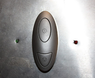
NEW POWER BUTTON: THOSE LITTLE THINGS

Well, ever since I started writing this blog and about ITINERA, I always said that it is a "handmade" robot. But somethings in the robot are too "handmade",  you know what I mean?

Let me put an example:


Yeah... that was the power switch of the robot, it was not a "handmade" job, it was a clumsy job (shame on me xD). So I decided to fix it.

I took a fancy power switch from an old computer, a couple of LEDs and attached it to the structure of the robot.


Then connected the power switch to the PC's mother board and one of the LEDs to the Power LED bay. The other LED is connected to the  motor's power source to indicate whether it is ON or OFF.


This is the result:


Looks much better :D

Tuesday, August 24, 2010

0

DAMAGE EVALUATION

In our world time is something we cannot fight. It goes by for everybody, even for robots.

So after all these years of inactivity and reusing components for other projects, the time has come to evaluate the damage caused to the robot.

Here is a list of the robot's components and its status:

ITEMSTATUS
StructureWorking
Control PC BoardMissing
Mini SSC IIWorking
Serial Motor InterfaceWorking
H-Bridge Motor controllerPartially Working - Can't move both motor wheels at the same time
FireWire InterfaceMissing
Ethernet InterfaceWorking
Wireless InterfaceMissing
Sound InterfaceMissing
MicrophoneMissing
Hard DriveMissing
Control PC Power SourceMissing
Motors Power SourceWorking
BatteryMissing
Stereo CameraWorking
Panoramic CameraMissing
BumpersWorking

Poor guy, almost half of the components were missing. Fortunately those components were easy to replace and some of them were not even needed. So, right now this is how ITINERA looks:


And thanks $DEITY: IT IS ALIVE!!

Friday, August 20, 2010

0

ITINERA: THE MAKING OF

Here is a video that shows a little bit about the making of this robot.

First it was designed by using the software Virtual Robot Simulator (http://robotica.isa.upv.es/virtualrobot). This software is similar in some ways to Microsoft's Robotic Developer Studio, the difference is that VRS was developed by the robotics group of UPV some years before MRDS and it is OpenSource.


After the digital design was approved, the actual assembly of the robot began... you should forgive me... I am a Computer Science Engineer not an Industrial or Mechanical Engineer, so the look was very "handmade" and the details not so polished... but, hey it works! It is not that bad :P 

Monday, August 16, 2010

1

ITINERA: WHAT WAS IT CAPABLE OF?

In this post I am going to roughly describe what the robot was able to do just before it was abandoned.

As mentioned in a previous post, the aim of the robot was to display the technology developed by ITI. Thanks to that technology the robot was able to perform several tasks related to speech recognition, speech synthesis, computer vision, biometry and navigation. But there was no specific task to be solved by the robot, it was just an exotic platform to display new technology.

The most basic task was to move around, this robot is a differential vehicle; it means  that it has two wheels set in the same axis and powered by independent motors. So, if both motors are set to the same speed and the same direction the robot will move straight forward (or backward depending on the direction of the motors). But, if both motors are set to the same speed and opposite directions then the robot will spin over itself. This vehicle configuration has been widely studied and its control is very simple. Based on this configuration I implemented a very simple layer of software to control the movements of the robot.

To complement the moving task, the robot had a series of bumpers and infrared beams that allowed it to detect collisions

Mounted on the top of the robot's head there was a camera pointing to an hyperbolic mirror. This mirror allowed the robot to see a 360 degrees picture of the scene. The purpose of this camera was to detect movements and then follow them.


In order to detect movements, first the image was flattened by using the Bresenham's algorithm. After that, the motion was detected by simple image subtraction (yeah, it is naive, but it was good enough).

This is the result of flattening the image and motion detection (you can see a vertical white line pointing out that I was moving in front of the robot)


Then there was the stereo camera. It was meant to be used to extract 3D information, but in fact only one of the images (eyes) was used. That eye was used to locate and identify faces, that means that the robot was able to know the identity of the person standing in front of it and track it.


Almost all the interaction with the robot was performed using a voice interface. That interface was implemented using ATROS (Automatically Trainable Recognition of Speech), a software developed by the PRHLT group of ITI. Thanks to this software (maybe someday ITI will release it under GPL license) it was easy to define a list of commands to be understood by the robot and associate an action to perform, for example:

  • move forward, move backward, move left, move right


  • follow me, who am I?

  • tell me the weather forecast, tell something funny

  • ....

The ability to speak was given by the Festival Speech Synthesizer. The Spanish voice was quite depressive but that made it funnier when you asked the robot's name and it answered   I tell you if you rub my hard drive


All the funny sentences and jokes came from Unix Fortune, a program that displays a random sentence from a database.

And that is pretty much it. Check this previous post if you want to see it in action.