Here is the result of the poll about the new voice for the robot.
And the winner is...(drum roll)....:
Many thanks for helping me to choose!
Showing posts with label ITINERA. Show all posts
Showing posts with label ITINERA. Show all posts
Thursday, September 16, 2010
Thursday, September 9, 2010
5
And can be tested by doing this:
Now I have a problem... I don't know which voice I like the most!!!
Could you help me to choose please?
Here you are the samples of the 3 voices:
Original Voice
Feminine Voice
Masculine Voice

VOICE SINTHESYS, TEXT TO SPEECH
As I mentioned on the post about damage evaluation of ITINERA, the sound interface was missing. But today the new one arrived. So, it is time to give back to the robot its ability to speak.
In order to do that, I installed the Festival Speech Synthesis System. Since the OS of the robot is Debian this task is quite easy:
$ sudo apt-get install festival festvox-ellpc11k
The package festvox-ellpc11k contains the default Spanish male voice, which is the voice that the robot had previously.
I also installed 2 new Spanish voices, developed by Junta de Andalucia for Guadalinex. Those were quite easy to install as well:
$ wget http://forja.guadalinex.org/frs/download.php/154/festvox-sflpc16k_1.0-1_all.deb
$ wget http://forja.guadalinex.org/frs/download.php/153/festvox-palpc16k_1.0-1_all.deb
$ sudo dpkg -i festvox-palpc16k_1.0-1_all.deb
$ sudo dpkg -i festvox-sflpc16k_1.0-1_all.deb
$ wget http://forja.guadalinex.org/frs/download.php/153/festvox-palpc16k_1.0-1_all.deb
$ sudo dpkg -i festvox-palpc16k_1.0-1_all.deb
$ sudo dpkg -i festvox-sflpc16k_1.0-1_all.deb
And can be tested by doing this:
$ festival
Festival Speech Synthesis System 1.96:beta July 2004
Copyright (C) University of Edinburgh, 1996-2004. All rights reserved.
For details type `(festival_warranty)'
festival> (voice_JuntaDeAndalucia_es_sf_diphone)
JuntaDeAndalucia_es_sf_diphone
festival> (SayText "Hola, soy la nueva femenina de itinera")
festival> (quit)
$ festival
Festival Speech Synthesis System 1.96:beta July 2004
Copyright (C) University of Edinburgh, 1996-2004. All rights reserved.
For details type `(festival_warranty)'
festival> (voice_JuntaDeAndalucia_es_pa_diphone)
JuntaDeAndalucia_es_sf_diphone
festival> (SayText "Hola, soy la nueva masculina de itinera")
festival> (quit)
Now I have a problem... I don't know which voice I like the most!!!
Could you help me to choose please?
Here you are the samples of the 3 voices:
Original Voice
Feminine Voice
Masculine Voice
Which voice do you like?
Sunday, September 5, 2010
3

I recommend you to read it, you will find much more details than in this post ;)
Here you can see a video demonstrating how it works, sorry for my Spanish accent xD
(CONTROLLING RKL298 WITH ARDUINO) ARDUINO: THE BEST PIECE OF HARDWARE EVER!
Arduino is an open-source electronics prototyping platform based on flexible, easy-to-use hardware and software. And it is also very cheap! Under 20€!

In a previous post I talked about an L298 based motor controller. It is the circuit that is going to replace a faulty motor controller of the robot ITINERA. Now I need a way to command the new motor controller via a PC serial port. The previous motor controller had a Serial Motor Interface, it costs over 50€ and it is not compatible with the new motor controller.
Another issue is that the robot is programmed to use the protocol of the old Serial Motor Interface and I would not like to change that program because it took me so long to build it :p
The solution is my new best friend: Arduino. I have never used it before but thanks to its features I could program it to do what I need in less than 1 hour... and the best of all... it worked at the first attempt!!!!
Here you have the source code, it could be useful if you want to reproduce this kind of motor control or if you just want to see how easy it is to program an arduino.
I recommend you to read it, you will find much more details than in this post ;)
/*
   Serial Motor Interface
   Author: Martin Peris-Martorell - www.martinperis.com

   Description: This program is a serial port motor interface.
   It is used to command an H-Bridge motor controller based on
   L298.
   This motor controller can be found at www.rkeducation.co.uk
   under the reference part number: RKL298 PCB

   The RKL298 PCB can control 2 DC motors. The control is achieved
   by using 6 control lines: ENA, IP1, IP2, ENB, IP3 and IP4.

   ENA, IP1 and IP2 are used to command the motor A
   ENB, IP3 and IP4 are used to command the motor B

   Wiring with arduino:

   RKL298 PCB |     Arduino
   -----------------------------
   ENA       <-> Digital port 12
   IP1       <-> Digital port 11
   IP2       <-> Digital port 10

   ENB       <-> Digital port 7
   IP3       <-> Digital port 6
   IP4       <-> Digital port 5

   A LED can be connected to digital port 13

   Serial port configuration: 9600 bauds

   Comunication protocol: Connect the arduino via USB to
   a PC, or via digital pins 0 and 1 to a serial port.

   Open the serial port for communication and send 3 bytes.
   The format is:

   Byte 0: 255  //Sync. signal
   Byte 1: Motor identificator. 0 for motor A, 1 for motor B.
   Byte 2: Command. A value between 0 and 63.
                    0       = Full stop (free running)
                    1 - 31  = Backward with PWM ( 1: slowest, 31: fastest)
                    32      = Full stop (active braking)
                    33 - 63 = Forward with PWM (33: slowest, 63: fastest)

  For example, if you want to move motor A backward at 50% of speed
  the command would be:  255 0 16
  If you want to stop motor A the command would be: 255 0 0


  This program is distributed under the terms of the GNU General Public License.

  Enjoy it.
*/


/* Declarations for serial communications */
int incomingByte[128];
int numBytes = 0;

/* Declarations for wiring */
int pinEN[2];
int pinIP1[2];
int pinIP2[2];


void setup(){
int i = 0;
//0 refers to Motor A; 1 refers to Motor B
pinEN[0] = 12;
pinEN[1] = 7;

pinIP1[0] = 11;
pinIP2[0] = 10;

pinIP1[1] = 6;
pinIP2[1] = 5;

//Set pin modes
for (i = 0; i < 2; i++){
pinMode(pinEN[i], OUTPUT);
digitalWrite(pinEN[i],HIGH);
pinMode(pinIP1[i], OUTPUT);
digitalWrite(pinIP1[i],LOW);
pinMode(pinIP2[i], OUTPUT);
digitalWrite(pinIP2[i],LOW);
}

//Light up the led
pinMode(13,OUTPUT);
digitalWrite(13,HIGH);

//Open serial port
Serial.begin(9600);
}

void loop(){
int i = 0;
int motor = 0;
int action = 0;

//Check for data in serial port
numBytes = Serial.available();
if (numBytes >= 3){

//Read all the data in the buffer
for(i = 0; i < numBytes; i++){
incomingByte[i] = Serial.read();
}

/* The data received should be: 255 M A
       Where:
        255 is the sync byte
        M is the motor number (0 or 1)
        A is the action (a number between 0 and 63)
    */
if (incomingByte[0] != 255 || incomingByte[1] < 0 || incomingByte[1] > 1 || incomingByte[2] < 0 || incomingByte[2] > 63){
Serial.flush();
return;
}

/* The received data is correct -> activate the appropriate pins */
motor = incomingByte[1];
action = incomingByte[2];

if (action == 0){
//Full stop (free running)
digitalWrite(pinIP1[motor],LOW);
digitalWrite(pinIP2[motor],LOW);
return;
}

if (action == 32){
//Full stop (active braking)
digitalWrite(pinIP1[motor],HIGH);
digitalWrite(pinIP2[motor],HIGH);
return;
}

if (action >= 1 && action <= 31 ){
//Reverse with PWM
analogWrite(pinIP1[motor],0);
analogWrite(pinIP2[motor],(action-1)*8);
return;
}

if (action >= 33 && action <= 63 ){
//Forward with PWM
action = action - 32;
analogWrite(pinIP1[motor],(action-1)*8);
analogWrite(pinIP2[motor],0);
return;
}

}

}
Here you can see a video demonstrating how it works, sorry for my Spanish accent xD
Tuesday, August 31, 2010
0


DO NOT REINVENT THE WHEEL!
Sometimes when you work in a complex robotic project you face the question: Should I build myself a certain part or should I buy a manufactured one?
Recently I faced that question, the robot ITINERA needs a new circuit to control 2 DC motors because the old one is malfunctioning. Then it came to my mind that some years ago I implemented such a circuit by using a self-made PCB board, an L298 integrated circuit and some other components (diodes, resistors, etc...)


So now I could build it again and use it, but lets think about it... if I buy all the components I would spend about 15€ and it would take me about 2 hours to build it. Time is money, so if we translate two hours of work into money, lets say that is equivalent to 40€. In total: 55€ (Not taking into account the time spent going to the store and getting the components)
In the other hand, performing a quick search on Internet you can find products matching your needs. In my case an L298 h-bridge with a price of 12,42€

I think, in this case, the answer to the question raised at the beginning of this post is pretty clear: Do not reinvent the wheel!!!
By the way, the circuit in the last picture is the one that will replace the faulty motor controller of ITINERA.
Saturday, August 28, 2010
0
NEW POWER BUTTON: THOSE LITTLE THINGS
Well, ever since I started writing this blog and about ITINERA, I always said that it is a "handmade" robot. But somethings in the robot are too "handmade", you know what I mean?
Let me put an example:

Yeah... that was the power switch of the robot, it was not a "handmade" job, it was a clumsy job (shame on me xD). So I decided to fix it.
I took a fancy power switch from an old computer, a couple of LEDs and attached it to the structure of the robot.

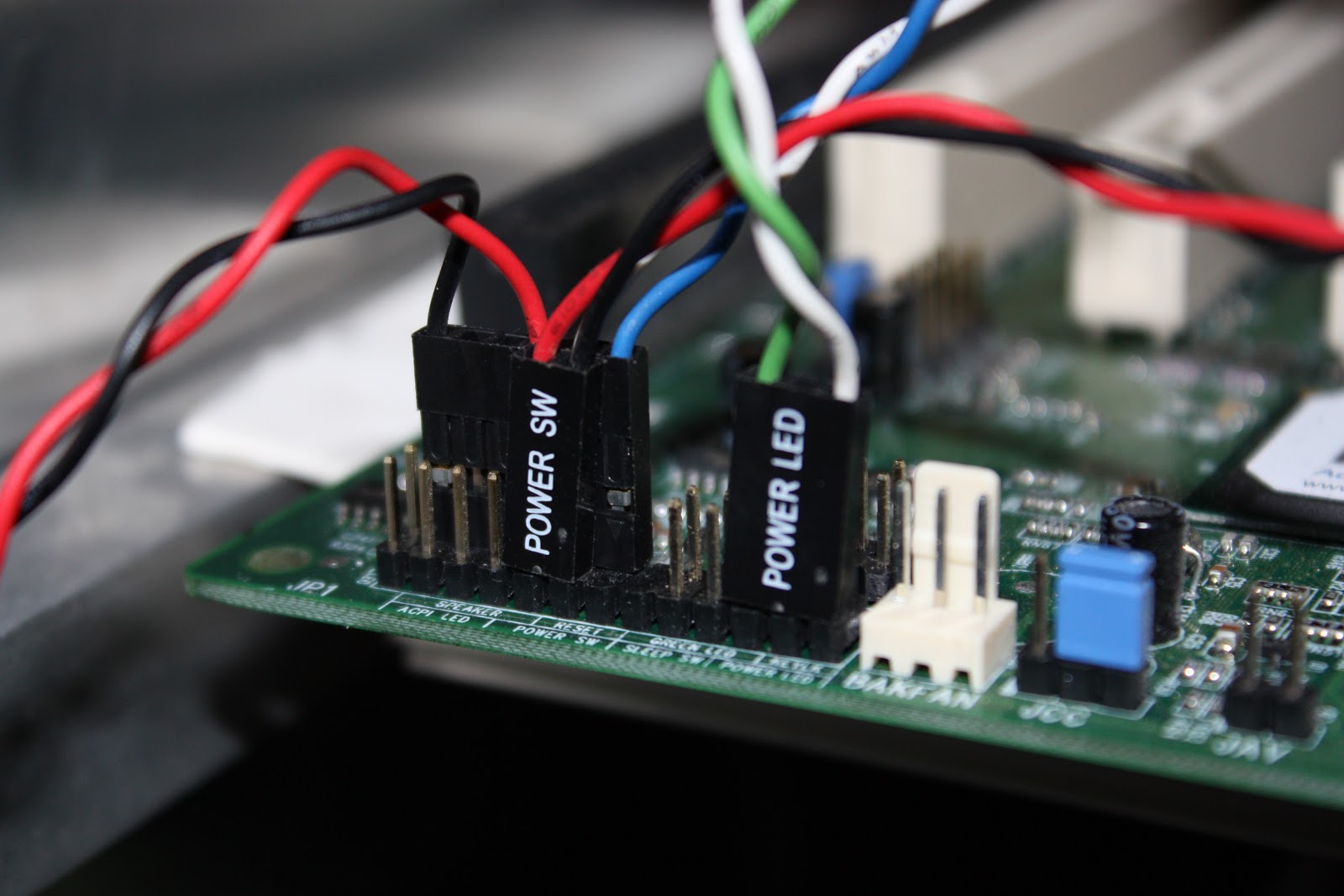
Then connected the power switch to the PC's mother board and one of the LEDs to the Power LED bay. The other LED is connected to the motor's power source to indicate whether it is ON or OFF.

This is the result:
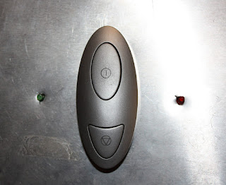
Looks much better :D
Let me put an example:

Yeah... that was the power switch of the robot, it was not a "handmade" job, it was a clumsy job (shame on me xD). So I decided to fix it.
I took a fancy power switch from an old computer, a couple of LEDs and attached it to the structure of the robot.

Then connected the power switch to the PC's mother board and one of the LEDs to the Power LED bay. The other LED is connected to the motor's power source to indicate whether it is ON or OFF.
This is the result:

Looks much better :D
Tuesday, August 24, 2010
0
Poor guy, almost half of the components were missing. Fortunately those components were easy to replace and some of them were not even needed. So, right now this is how ITINERA looks:
And thanks $DEITY: IT IS ALIVE!!
DAMAGE EVALUATION
In our world time is something we cannot fight. It goes by for everybody, even for robots.
So after all these years of inactivity and reusing components for other projects, the time has come to evaluate the damage caused to the robot.
Here is a list of the robot's components and its status:
| ITEM | STATUS |
| Structure | Working |
| Control PC Board | Missing |
| Mini SSC II | Working |
| Serial Motor Interface | Working |
| H-Bridge Motor controller | Partially Working - Can't move both motor wheels at the same time |
| FireWire Interface | Missing |
| Ethernet Interface | Working |
| Wireless Interface | Missing |
| Sound Interface | Missing |
| Microphone | Missing |
| Hard Drive | Missing |
| Control PC Power Source | Missing |
| Motors Power Source | Working |
| Battery | Missing |
| Stereo Camera | Working |
| Panoramic Camera | Missing |
| Bumpers | Working |
Poor guy, almost half of the components were missing. Fortunately those components were easy to replace and some of them were not even needed. So, right now this is how ITINERA looks:
And thanks $DEITY: IT IS ALIVE!!
Friday, August 20, 2010
0
ITINERA: THE MAKING OF
Here is a video that shows a little bit about the making of this robot.
First it was designed by using the software Virtual Robot Simulator (http://robotica.isa.upv.es/virtualrobot). This software is similar in some ways to Microsoft's Robotic Developer Studio, the difference is that VRS was developed by the robotics group of UPV some years before MRDS and it is OpenSource.
After the digital design was approved, the actual assembly of the robot began... you should forgive me... I am a Computer Science Engineer not an Industrial or Mechanical Engineer, so the look was very "handmade" and the details not so polished... but, hey it works! It is not that bad :P
Monday, August 16, 2010
1

Then there was the stereo camera. It was meant to be used to extract 3D information, but in fact only one of the images (eyes) was used. That eye was used to locate and identify faces, that means that the robot was able to know the identity of the person standing in front of it and track it.
ITINERA: WHAT WAS IT CAPABLE OF?
In this post I am going to roughly describe what the robot was able to do just before it was abandoned.
As mentioned in a previous post, the aim of the robot was to display the technology developed by ITI. Thanks to that technology the robot was able to perform several tasks related to speech recognition, speech synthesis, computer vision, biometry and navigation. But there was no specific task to be solved by the robot, it was just an exotic platform to display new technology.
The most basic task was to move around, this robot is a differential vehicle; it means that it has two wheels set in the same axis and powered by independent motors. So, if both motors are set to the same speed and the same direction the robot will move straight forward (or backward depending on the direction of the motors). But, if both motors are set to the same speed and opposite directions then the robot will spin over itself. This vehicle configuration has been widely studied and its control is very simple. Based on this configuration I implemented a very simple layer of software to control the movements of the robot.
To complement the moving task, the robot had a series of bumpers and infrared beams that allowed it to detect collisions.

Mounted on the top of the robot's head there was a camera pointing to an hyperbolic mirror. This mirror allowed the robot to see a 360 degrees picture of the scene. The purpose of this camera was to detect movements and then follow them.
In order to detect movements, first the image was flattened by using the Bresenham's algorithm. After that, the motion was detected by simple image subtraction (yeah, it is naive, but it was good enough).
This is the result of flattening the image and motion detection (you can see a vertical white line pointing out that I was moving in front of the robot)


Then there was the stereo camera. It was meant to be used to extract 3D information, but in fact only one of the images (eyes) was used. That eye was used to locate and identify faces, that means that the robot was able to know the identity of the person standing in front of it and track it.
Almost all the interaction with the robot was performed using a voice interface. That interface was implemented using ATROS (Automatically Trainable Recognition of Speech), a software developed by the PRHLT group of ITI. Thanks to this software (maybe someday ITI will release it under GPL license) it was easy to define a list of commands to be understood by the robot and associate an action to perform, for example:
- move forward, move backward, move left, move right
follow me, who am I?
- tell me the weather forecast, tell something funny
- ....
The ability to speak was given by the Festival Speech Synthesizer. The Spanish voice was quite depressive but that made it funnier when you asked the robot's name and it answered I tell you if you rub my hard drive
All the funny sentences and jokes came from Unix Fortune, a program that displays a random sentence from a database.
Monday, August 9, 2010
0
ITINERA: A LOWCOST HANDMADE ROBOT
ITINERA was the robot that I built as Degree Project five years ago at ITI (Instituto Tecnológico de Informática). The aim of this robot was to integrate all the technology developed at ITI in subjects like Speech Recognition, Computer Vision and so on.
The thing you should keep in mind when looking at ITINERA is that it was a low cost project and handmade.
Basically it is a regular PC with an aluminum structure, motors, wheels, cameras,some control circuits and software.
Here you can see ITINERA in action (thanks to Luis for the video):
It was taken to several events and it claimed the attention of a lot of people. Unfortunately I was assigned to other projects and ITINERA was abandoned :(
Now, five years later, I have a couple of months free and I wanted to rescue that robot and do some upgrading. I talked to the people of ITI and they, very gently, lend it to me so I could work with it at home.
After all this years of being in a corner it was in really bad shape. Now I started to repair and reprogramme it (I am ashamed of the software I wrote 5 years ago xD).
Monday, August 2, 2010
0

HELLO WORLD!
This is the first post in this blog. You see, I have always been an enthusiast of robotics, computers and technology and I always wanted to share that enthusiasm with the rest of the world.
Recently I rescued a robot that I built five years ago (2005). While restoring the robot it came to my mind that this could be the motivation I needed to start a blog, describe the project as it grows and talk a little bit about things related to the world of robotics, computer vision, artificial intelligence and technology.
So, here it is. If you'd like to, you are more than welcome to come and visit this site anytime.
Subscribe to:
Posts (Atom)